Download PDF General Info Get Quotation
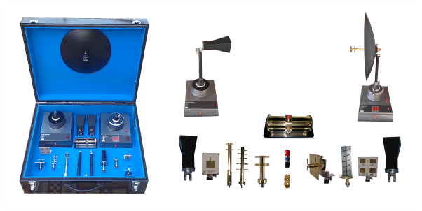
Antenna Trainer AT-5000 is a low cost high performance antenna training system. It is designed to be used in two distinct ways; for teaching and demonstrating common antenna configurations at all levels of study, and as a design tool by those engaged in research and development of projects in communication.
Antenna Trainer AT-5000 has been designed to act as basic tool for carrying out experiment in the field of antenna for Technical Colleges and Engineering Universities undergraduate and graduate courses. AT5000 comprises of C-Band microwave transmitter, microwave receiver with Digital Voltmeter Display, turn table and set of eight different type of antennas. The transmitter and receiver units have been built in power supplies and hence each is powered from 220 VAC 50Hz supply. Various antennas are mounted directly on the receiver for pattern measurement.
AT-5000 is stand alone, versatile table top system that provides hands on experimentation, understanding, working of Antennas, and plot their polar plots without any high frequency equipment.
Training system includes modular mechanical units construction forming various antennas, transmitting unit and detector unit. Emphasis is placed on the basic design of microwave antennas, pattern in principal planes, polarization and beam width calculation.
Features
- Stand alone, Low cost system
- Modulated 5.15GHz DRO source
- No ancillary equipment required
- Bench-top operation Safe low power output
- Simple, robust stands for antenna mount
- Conveniently packed for inventory control
- More antennas can be added on the users course requirement
- Safe low power output
Accessories
- C-BandTransmitter
- C-Band Receiver
- Slotted Line
- Dipole Antenna
- Pyramidal HornAntenna
- Yagi-UdaAntenna
- Helical Antenna
- Microstrip Antenna
- Paraboloidal Reflector Antenna
- 4 Element MicrostripArrayAntenna
- CablesSMA(m) toSMA(m)
- 25 dB Atenuattor
List of Experiments
- Familiarization with Antenna Trainer
- Study of Antenna Polarization, Axial Ratio and Tilt Angle of a circularly polarized antenna.
- Study of Dipole antenna and its radiation pattern
- Study of Horn antenna and its radiation pattern
- Measurement of the Gain of Horn Antenna
- Study of Yagi antenna and its radiation pattern
- Study of Helical antenna and its radiation pattern
- Study of Microstrip Antenna and its radiation pattern
- Study of Paraboloidal Reflector Antenna and its radiation pattern
- Study of Four Element Rectangular Patch Array Antenna
- Study of Double Dipole Array Antenna
- Study of slotted line and measurement of Wavelength and Frequency
- Measurement of VSWR using Slotted line
- Measurement of Unknown Impedance
Specification
C-BandTransmitter
- Center Frequency: 5150MHz
- Output Power: 10 dBm
- RF.source: RF.source: Dielectric Resonator Oscillator
C-Band Receiver
- Center Frequency: 5150MHz
- Band width: 50MHz
- Sensitivity: -30dBi
- Motor rotation: 0º to 180º with 5º step
Pyramidal Horn Antenna
- Gain: 7.42dBi
- HP Beam width: 62
- Polarization: Linearº
Yagi-Uda Antenna
- Driven elements: Four element array
- Polarization: Linear
Microstrip Patch Antenna
- Gain: 6dBi
- Effective Angle: 125º
Microstrip Array Antenna
- Gain: 12dBi
- Patch Elements: 4
Parabolic Reflector Antenna
- Aperture efficiency: 50 %
- Diameter: 31 cm
- Directivity: 21.5dBi
- Feed: Dipole disk feed
Helical Antenna
- AR: 1.1
- Directivity: 14.6
- HPBW:37.5º
- FNBW:83º
Di-pole Antenna
- Directivity: 1.64
- Impedance: 50 Ohm
- Pattern: Omni directional
- Polarization: Linear
Double Di-pole Array Antenna
- Directivity: 7.5 dBi
- Impedance: 50 Ohm
- Polarization: Linear
Double Stub Tuner
- Length: 7cm
Attenuator
- Attenuation: 30dB
- Tolerance: ± 0.5dB
- Peak Power: 2 watts

