Download Software Download PDF General Info Get Quotation
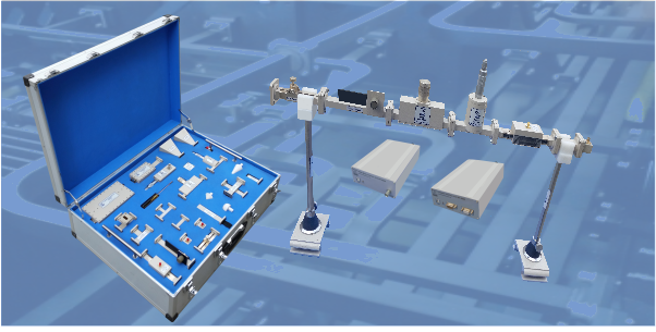
Microwave Trainer WT-9000 is a low cost high performance training system. It is designed to be used in two distinct ways; for teaching and demonstrating common waveguide configurations at all levels of study especially for Technical Colleges and Engineering Universities for undergraduate and graduate courses., It is also used as a design tool for those engaged in research and development of projects in communication.
This training system allows the user to investigate the principles of microwave transmission systems, such as those used in radar and communications links. It is a precision-made system, which uses waveguide components to illustrate the essential elements within this field of study. We use rectangular copper waveguide WR75. The inside of the waveguide is silver plated to make it more conductive. A standard flange is use to connect the components of the trainer with each other.
Features
- Stand alone, Low cost system
- 11 GHz Synthesized Source
- GUI Based Computer Interface
- Bench-top operation
- Simple, robust stands mount
- Wavelength & Phase Velocity Measurements
- Synthesized PLL Source
- Conveniently packed for inventory control
- More Microwave Accessories can be added on the users course requirement
- Safe low power output
Accessories
- X-Band Synthesized Source
- Waveguide Detector
- Cavity Resonator
- Matched Load
- Short Circuit
- Stub Tuner
- Slotted Line
- Series Tee
- Shunt Tee
- Hybrid/Magic Tee
- Guide Connector
- Directional Coupler
- Horn Antennas
- Coaxial Cable
- Wave guide-coaxial Adapter
- Precision Attenuator
- Variable Attenuator
- Waveguide Twist
- VSWR Meter
- Computer Interface Unit
- Software CD and Manual
List of Experiments
- Introduction of a microwave waveguide bench and measurement of source frequency and wavelength
- Measurement of Voltage and Standing Wave Ratio (VSWR)
- Measurement of impedance and impedance matching
- Impedance measurement of Inductive and Capacitive Irises
- Horn Antenna Investigation
- Measurement of Dielectric Constant
- Use of a directional coupler in power transmission and reflective measurements
- Series, Shunt and Hybrid T junctions
- Waveguide to coaxial transformers
- Microwave Radio link Investigations
Specification
X-Band Synthesized Source
- Center Frequency: 11 GHz ± 200 MHz
- Output Power: 10 mW Typical
- Pulse Mode Operation
Receiver/Power Meter
- Center Frequency: 11 GHz
- Band width: 10-13 GHz
- Sensitivity: -45 dBm
- Dynamic range: 50dB
Match Load
- S11: >25 dB
- Band Width: 11-13 Ghz
Precision Attenuator
- Insertion Loss: 1-2 dB
- Band Width: 11-13GHz
- Return Loss > 20dB
Directional Coupler
- Directivity: 15dB
- Coupling: 20dB
Waveguide to Coax Adopter
- Return Loss >20 dB
- Insertion Loss: 1dB
- Connector: SMA
Rectangular Waveguide
- S11:> 20dB
- S12: < 1 dB
- Band Width: 11-13 Ghz
Phase Shifter
- S11: > 15 dB
- S12: > 15 dB
- Calibration: 11 GHz
Series E Plane Tee
- S11, S22, S33: > 20 dB
- S12, S13: 3.5 dB
- Phase: 180º
- Band Width: 11-13 GHz
Shunt H Plane Tee
- S11, S22, S33:> 20 dB
- S12, S13: 3.5 dB
- Phase: 0º
- Band Width: 11-13 GHz
Hybrid Magic Tee
- S11:> 10 dB
- Isolation: 20 dB
- Band Width: 11-13 Ghz
Slotted Line
- S11: > 20 dB
- Insertion Loss< 0.5dB
- Resolution: 0.5 mm
Variable Attenuator
- Return Loss > 20 dB
- S12: 1-20 dB
- Resolution: 1 dB
- Accuracy: + 1.5 dB
Horn Antenna
- Gain: 16 Db
- S11: 20 dB
- Beamwidth: 30º E& H
- Type: Pyramidal

